Solar load: simulating the deformation of interior plastic parts
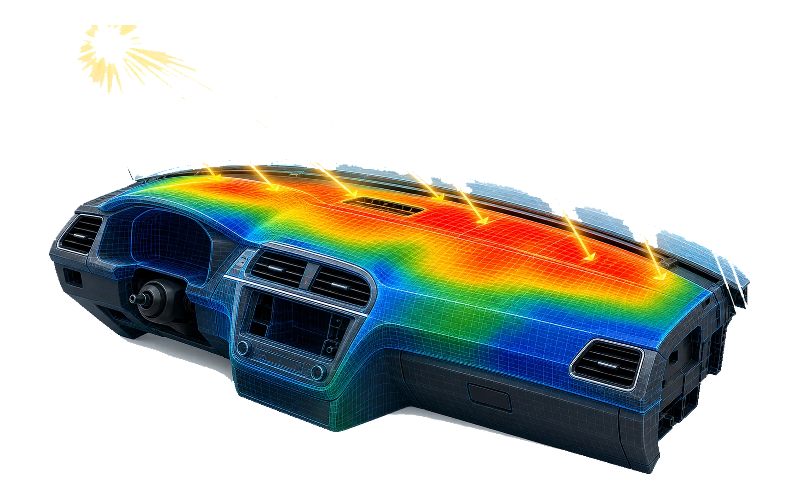
Behind glazing, a trim can exceed 100°C in full sun. A two-step thermomechanical simulation methodology reproduces the OEM solar test, from meshing to post-processing, and was transferred to the client's teams.
The challenge
Behind glazing in full sun, interior plastic parts (instrument panels, trims, window scrapers) locally exceed 100°C and deform. Full-vehicle solar tests come late in the project and are costly. The need: a simulation methodology that faithfully reproduces the OEM test and that in-house analysis teams can run autonomously, from the CAD stage.
Step 1: thermal analysis
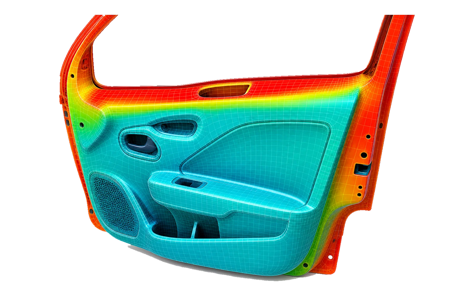
The temperature map is obtained through one of two routes, depending on available data: the radiative method, where the test's radiant panels are modeled as infrared sources in a cavity (70°C ambient), or the imposed temperature-band method when measurements exist. The thermal mesh is a quad shell mesh built on the parts' neutral fiber, of about 5,000 elements.
Step 2: thermomechanical analysis
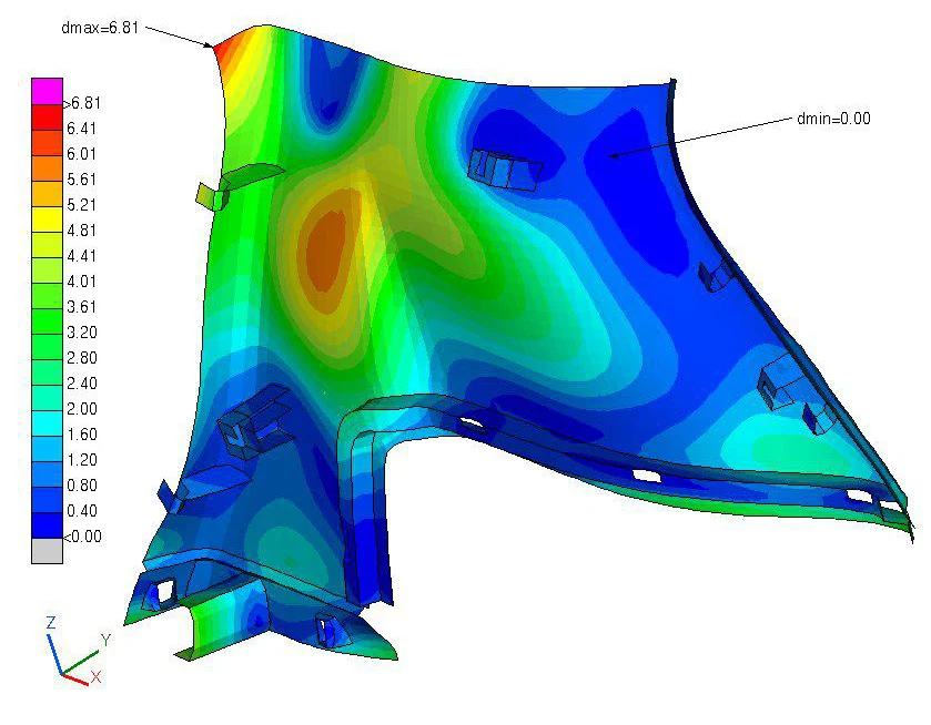
The temperature field is transferred by submodeling to the finer mechanical mesh (about 20,000 elements), then a nonlinear computation evaluates stress and deformation. The part's real attachments (clips, screws, staples, rivets) are modeled as multi-point rigid elements validated with the design teams, and part-to-part contacts are accounted for. Initial temperature: 23°C.
Results
- Thermal maps consistent with the reference solar test, up to 105°C in exposed areas
- Displacements, reaction forces, stress and deformation available for every configuration, before any physical test
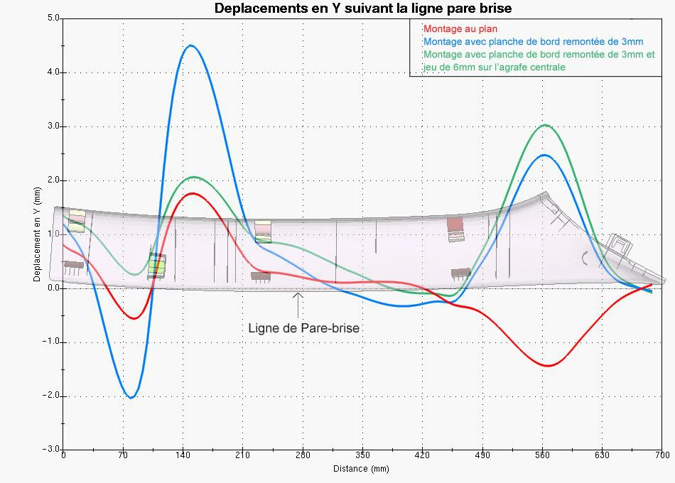
- Design choices settled on curves: instrument panel position and clip clearances compared along the windshield line
- Mesh quality criteria differentiated between thermal and mechanical steps, for a robust pipeline
- Step-by-step documented procedure, from meshing to post-processing, transferred to the client's in-house teams